Fire Pump Curves and Performance Data Explained
Let me paint a scene for you. Picture a familiar, soothing narrator sitting in a leather chair, deep voice humming in your ears as he says: “Now, folks… today, we’re going to dive into something most people avoid—fire pump curves.” I get it—reading fire pump performance data isn’t exactly Netflix-binge material. But when you’re dealing with fire safety systems protecting high-rise towers or sprawling manufacturing campuses, it becomes a keystone topic. Trust me, once you understand how to read fire pump performance curves, it’s not just technical know-how—it’s a life-saving superpower with a briefcase.
Let’s dispel the myth that only engineers fluent in Hydraulic-ese can decipher those swoopy, slanted lines on a performance graph. This isn’t a riddle, folks. It’s a reliable blueprint for understanding how a fire pump will behave under real pressure—literally. Grab a cup of coffee. This is going to be a smooth ride, and who knows? There may be a Marvel reference or two coming your way. Let’s roll.
The Heartbeat of Your Fire Protection System
So, why do these curves matter? Imagine a firefighter suiting up and charging into action—only to find the water pressure is… meh. That’s not just disappointing. That’s disastrous.
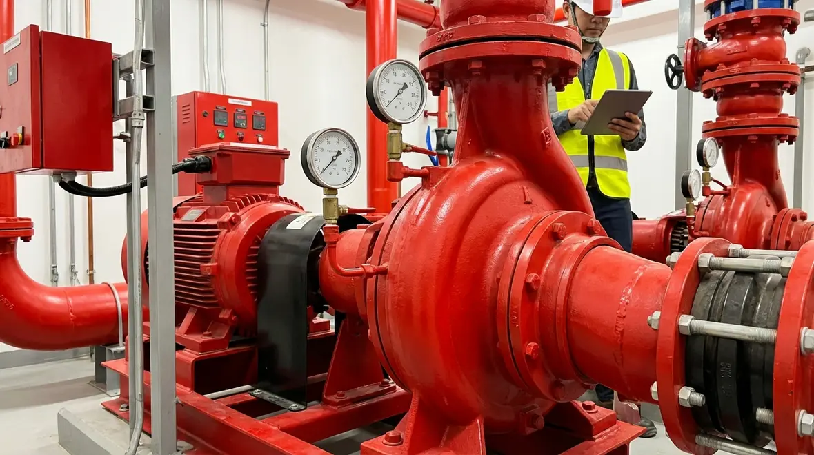
Your fire pump, most likely a centrifugal workhorse, is the essential backup singer to your sprinkler and hydrant systems. It doesn’t just exist to meet code; it’s designed to maintain pressure when the heat literally turns up.
Fire pump performance curves show how your pump will react at different flow rates, pressures, and efficiencies. This isn’t sci-fi. This is science that speaks directly to whether an upper-floor office suite will be doused or devoured. For commercial and industrial buildings, where downtime means potentially millions, you’d better believe this matters.
How to Read Fire Pump Performance Curves: Breaking Down the Graph
Now, let’s break down that delicious omelet of a graph you’ve been avoiding on every pump datasheet. Here’s what’s on the plate:
- Flow (GPM): The horizontal axis. This tells you how many gallons per minute the pump can handle.
- Head (Pressure): The vertical axis. This shows how much pressure (in feet or psi) the pump can deliver at various flow rates.
- Efficiency Curve: Usually a hilly-looking line that tells you how well your pump performs at each stage.
- Brake Horsepower (BHP): Think of it as the fuel cost—or how much power the pump engine needs.
- Net Positive Suction Head Required (NPSHr): A tongue twister that basically ensures your pump doesn’t eat air when it should be drinking water.
Every curve tells a story. At the beginning of the flow line, pressure is high, but as you increase the flow rate, pressure falls. Somewhere in the middle, the pump hits its sweet spot: peak efficiency, minimal energy use, and ideal performance. Like the perfect bass line in a jazz solo.
Quick Visual Checklist
- Find the rated point on the flow axis.
- Trace up to the head curve: that’s your rated pressure.
- Check where that point lands on the efficiency curve.
- Cross over to the BHP curve to size your driver.
- Glance at NPSHr and confirm your suction conditions can handle it.
What Commercial Engineers Should Look for
If you’re sitting atop a 30-floor hospital or an industrial plant with enough equipment to power a NASA base, one size definitely doesn’t fit all. Your needs are specific. Here’s what to focus on:
- Rated Flow and Pressure: Choose a pump that meets your demand at worst-case scenario conditions. Think peak fire demand — not Tuesday lunch shift.
- Efficiency Sweet Spot (BEP): The Best Efficiency Point should align with your building’s day-to-day hydraulic needs. It’s the jazz solo again. Everything hums in harmony here.
- Curve Overlap: Some manufacturers overlay multiple curves. That’s their way of saying, “Here’s your choice, depending on your horsepower setup and impeller trims.” Welcome to the Hilfiger section of pump design.
And please, whatever you do—if your required flow rate ends up in the uncharted territory beyond the pump curve, don’t “YOLO” it. That’s where cavitation, failure, and possibly the ghost of OSHA violations reside.

How to Read Fire Pump Performance Curves for Testing and Commissioning
You’ve selected the pump. It’s installed. Champagne corks pop. But now comes the real deal: testing. You’ll want to match the data from your onsite flow testing with your pump’s performance curve. If the field points are off, it’s not just a “meh,” it’s a full-blown sabotage mission against your safety plans.
Here’s the strategy:
Pressure Matching
Does your system deliver the correct psi at expected flow GPM? If the pressure is too low, your pump could be underperforming—or your suction source could be insufficient.
Efficiency Check
Tracking efficiency tells you whether your electrical bills will spike or your diesel tank will weep every month. A slipping efficiency curve usually means wear and tear—or poor choice to begin with.
Fire code standards such as NFPA 20 or FM Global requirements may demand documentation of this test data. You can’t fake it till you make it here. The fire marshal? Oh, they’re the original LinkedIn influencers of the fire life safety world—and they show up with checklists.
Debunking Common Myths About Fire Pump Curves
Myth 1: Bigger pumps are always better.
Wrong, my friend. That’s the Hulk-smash approach to design. Oversizing creates inefficiencies, rapid cycling, and may even void warranties if not paired with proper system components. Think Thor’s hammer in Ant-Man’s apartment.
Myth 2: Any pump curve will do for my retrofit.
No, no, and a thousand times no. Your existing pipe system, elevation changes, and flow demands must match the pump’s curve precisely. Your building isn’t a test site for guesswork.
Myth 3: Pump curves are just paper specs.
They’re not some Hogwarts scroll. They represent hours of R&D, performance testing, and engineering design. Ignoring them is like ignoring the GPS during rush hour traffic in Los Angeles. You’re going to get stuck. Only in this case, maybe with a building full of smoke.
Fire Pump Curve Selection in Real Applications
Let me share a real scenario. A multi-million square foot assembly plant hired us last year. Beautiful place. Cutting-edge robotics. But their contractor was about to install a pump that operated outside of its ideal performance range for 80% of the system demand. That’s like hiring Kanye for elevator music.
We corrected the pump selection to place the most-used flow rate smack in the middle of the curve. Result? Smoother starts, lower stress on the impeller, and a system that triggered less often but responded faster. Safety went up. Maintenance costs went down. The operations manager cried tears of relief. Probably allergies. Definitely not emotion. (It was emotion.)
FAQ: Understanding Fire Pump Curves and Performance Data
Conclusion: Walk Away With Confidence, Not Confusion
So now you know how to read fire pump performance curves like a pro. You’re not just checking boxes—you’re protecting assets, uptime, and lives. Commercial and industrial systems aren’t toys. They demand precision. So when it’s time to evaluate or commission your fire pump, lean in. Don’t just hope the curve works in your favor—make sure it does. Contact the experts at FirePumps.org for tailored analysis, reliable testing, and top-tier service that keeps your building safer than Batman’s utility belt.