EN 12845 Fire Pump Room Ventilation Requirements
When I look at a fire protection system, I never stop at the pump alone. I look at the EN 12845 room as a full working space, because the pump, the driver, the controls, and the heat they create all need the right air around them. If the room cannot breathe, the system can suffer, and that is a very expensive way to learn a lesson. In commercial and industrial facilities, ventilation is not a side note. It is part of the survival plan, plain and simple.
Treat the EN 12845 room as a critical asset, not a spare corner. The better the space, the more likely the pump set is to work when the building needs it most.
What EN 12845 expects from pump room ventilation
EN 12845 expects the fire pump room to stay cool, dry, and fit for reliable operation. In simple terms, I want enough fresh air to remove heat from the pump set, the diesel engine, and any support equipment. At the same time, I need to avoid dust, fumes, rain, and anything else that can mess with the system. The standard does not ask for a fancy spa retreat for the pump, but it does demand a space that supports safe performance.
Ventilation must help keep the room temperature within a safe range for the installed equipment. If I use a diesel driven pump, I pay even more attention, because the engine adds heat fast. As a result, I need both incoming air and warm air removal to work together. One without the other is like Batman without Robin, or a coffee machine with no coffee. Technically present, yet deeply unhelpful.
Key performance goals for the EN 12845 room
For the typical EN 12845 room, I expect:
- Temperature controlled so that pumps, engines, and control panels stay within their rated limits
- Ventilation paths that do not let fumes or exhaust build up near people or equipment
- Openings and ductwork that resist rain, snow, and unwanted debris entering the room
- Stable conditions that allow routine testing without overheating the pump set
How I size airflow for a fire pump room
I start by checking the heat load from the pump room equipment. Then I look at room size, ambient temperature, engine type, and the way air moves through the building. In practice, I want the system to pull in enough cool air and push out hot air without creating dead spots. Those dead spots trap heat, and heat hates reliability almost as much as a bored security guard hates night shift.
For EN 12845 fire pump room ventilation requirements, I also check whether the room has natural ventilation, mechanical ventilation, or a mix of both. Natural airflow can work in some projects, but only when the layout supports it. Mechanical systems give me more control, so I often prefer them in larger commercial and industrial facilities where the stakes are higher and the loads change more often.
Air in
Fresh air must enter freely and in enough volume to feed the pump room. I place intakes where they are unlikely to be blocked by future works, parked vehicles, or creative storage solutions.
Air out
Hot air must leave the room without recirculating back into the intake path. Exhaust points go high and as far as practical from intakes, roofs, or walls where heat can simply drift straight back in.
Natural vs mechanical ventilation
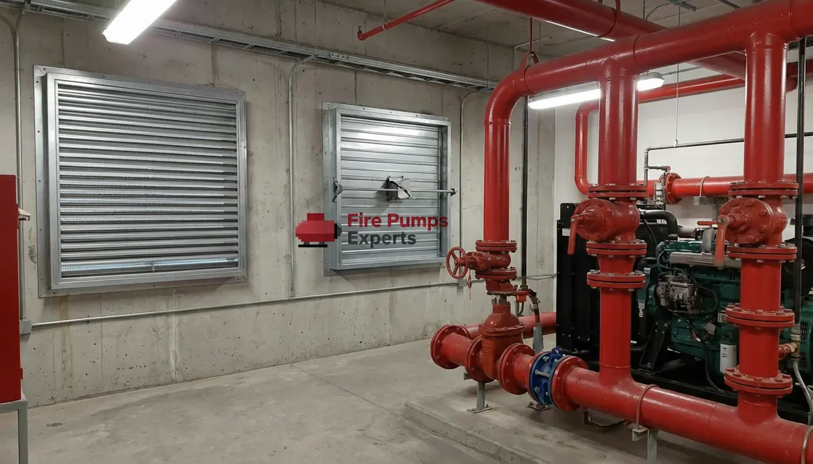
In some smaller installations, a well‑positioned louvered EN 12845 room with clear crossflow can meet the needs with natural ventilation. In most serious commercial or industrial buildings, though, the safer path is usually mechanical extraction and supply sized to the engine manufacturer data and heat rejection figures.
Why temperature and airflow matter in practice
I treat temperature control as a reliability issue, not a comfort issue. If the room gets too hot, the diesel engine may struggle, batteries may age faster, and control gear can suffer. Over time, that can lead to nuisance faults or worse, a pump that does not perform when needed. That is not the kind of drama anyone wants during a fire emergency. I prefer my excitement in movies, not in plant rooms.
Airflow also affects corrosion and moisture. A damp room can damage metal parts, wiring, and controls. Therefore, I aim for steady ventilation that keeps the room stable across seasons. Winter and summer both bring different problems, and I plan for both. Good ventilation keeps the room from swinging between hot, wet, and stale, which is no way to run critical protection equipment.
Hidden side effects of poor ventilation
- Condensation on cold pipework leading to surface corrosion and dripping onto controls
- Hot spots around engines that distort plastic components or cable insulation
- False alarms or unexplained shutdowns from overheated panels and electronics
- Unpleasant working conditions that discourage proper inspection and testing
Common design mistakes I avoid
I see the same errors again and again. First, some designs place intake and exhaust too close together, so the room ends up recycling its own hot air. That is a classic self own. Second, some rooms rely on vents that are too small or blocked by other plant items. Third, some projects forget that doors, louvers, and grilles also affect the airflow path. Every opening matters.
I also avoid mixing the fire pump room with unrelated storage or equipment that can create heat, dust, or clutter. EN 12845 room planning works best when the space stays dedicated to fire protection equipment. If a room starts doing ten jobs, it usually does none of them well. I like a room with a clear purpose, a clean path for air, and enough access for inspection and maintenance.
Checklist of issues to hunt for in an EN 12845 room
- Intakes or exhausts located behind screens, fences, or “temporary” barriers
- Grilles sized for appearance instead of calculated airflow
- Louvers installed without bird or insect screens where they are clearly needed
- Flexible duct runs that fold, sag, or kink on the way to the room
- Shared spaces with storage, workshop tools, or random building services
How I check compliance on site
On site, I verify the room layout, vent locations, fan capacity if used, and the route for intake and exhaust air. I also check that the vents remain open and that nothing from later building work has blocked them. This happens more often than people admit. A nice new wall, a stack of materials, or a “temporary” cover can quietly sabotage the whole system.
I also review the manufacturer data for the pump set and engine, because the equipment itself helps set the ventilation target. In some projects, I work with the building team to make sure the ventilation supports both daily conditions and emergency running. If you want a useful technical reference for industrial and major property fire pump rooms, I recommend reviewing the EN 12845 fire pump room guidance from a specialist source that focuses on commercial systems.
Simple on‑site ventilation walk‑through
- Stand at the intake and trace the airflow path across the EN 12845 room, all the way to the exhaust.
- Confirm that emergency access routes and test routes do not obstruct vents or ducts.
- Check fan nameplates against the design duty and any running time expected during a fire.
- Look for later additions: cable trays, pipework, partitions, or shelving that changed the original airflow.
- Confirm maintenance access so that filters, grilles, and fans can be cleaned without heroic effort.
FAQ: EN 12845 fire pump room ventilation
Below are quick answers to questions that often appear when planning or reviewing a fire pump installation and its ventilation.
Final thoughts and next step
If you want your fire pump to perform when it matters most, I suggest treating ventilation as a core part of the design, not an afterthought. I would review the room layout, airflow path, heat load, and access for maintenance before you sign off any project. For major commercial and industrial properties, that small step can save time, money, and stress later. If you need expert support, now is the time to act and get the room right.